



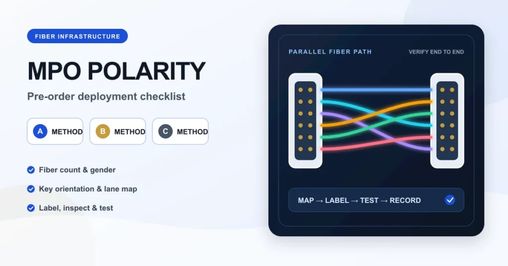
MPO polarity must be decided before fiber trunks, cassettes and patch cords are ordered. The correct method preserves the transmit-to-receive path from one transceiver to the other while keeping connector gender, key orientation and fiber count compatible. A deployment can use Method A, B or C successfully, but mixing components from different methods without a documented plan is a common cause of failed links, emergency patching and difficult troubleshooting.
What an MPO Polarity Method Controls
A parallel-fiber channel contains multiple fiber positions in one connector. At the system level, every transmit lane must arrive at the matching receive lane. The polarity method defines how fiber positions are carried or flipped across trunks, adapters, cassettes and equipment cords. It is therefore a channel design decision, not just a patch-cord choice.
The three established approaches are often described as follows:
| Method | Typical trunk behavior | Where the polarity change occurs | Planning priority |
|---|---|---|---|
| Method A | Position 1 remains position 1 through a straight-through trunk | A-B patching or another defined component completes the Tx/Rx flip | Label the different cord types so they cannot be swapped |
| Method B | The trunk reverses all fiber positions | The array reversal is built into the Type-B channel | Verify transceiver lane mapping and single-mode APC key orientation |
| Method C | Adjacent fiber pairs are flipped | The pairwise crossover is built into the trunk | Confirm that the system is duplex-pair based and does not require a different parallel mapping |
These descriptions are useful for procurement, but the final channel must be checked against the equipment vendor’s port definition. The Fluke Networks guide to 12- and 8-fiber MPO polarity emphasizes that method, gender, fiber count and connector orientation must be considered together. TIA guidance also distinguishes array polarity and connector configurations; a letter on a purchase order alone is not a complete specification.
Five Decisions to Lock Before Ordering
1. Base-8, Base-12 or another fiber count
Start with the optical interface and lane architecture. A four-lane transmit and four-lane receive application commonly uses eight active fibers, while legacy or distribution infrastructure may use 12-fiber trunks. A 12-fiber connector does not automatically mean all 12 fibers are active. If Base-8 and Base-12 components are mixed, document the conversion point and any unused positions. Do not assume a cassette will correct a mismatch.
2. Connector gender and alignment pins
MPO connectors are either pinned or unpinned. A connection requires one pinned side and one unpinned side; two pinned connectors cannot mate correctly, while two unpinned connectors lack alignment. Equipment ports and cassettes can differ, so record the interface at every endpoint. Use “pinned” and “unpinned” on the bill of materials instead of relying only on the less precise words male and female.
3. Key orientation and end-face type
Key-up and key-down orientation affects fiber position mapping. Single-mode MPO systems frequently use angled physical contact interfaces, and the adapter orientation must support the intended end-face contact and polarity. Never substitute UPC and APC interfaces. The connector color is a helpful field cue, but the purchase specification should state the actual polish and key orientation.
4. Native parallel optics or breakout operation
A native parallel link maps multiple transmit lanes directly across the MPO channel. A breakout link converts one high-density port into multiple duplex endpoints. Those two applications can use similar-looking hardware but require different lane plans. Record the host port, module type, destination ports and required breakout sequence before selecting a harness or cassette.
5. The complete channel, not one component
Draw the channel from equipment port to equipment port. Include every trunk, adapter, cassette, module, harness and patch cord. Add the method, fiber positions and connector details at each junction. This one-page diagram is more useful to installers than a product list with no lane mapping.

Pre-Order MPO Bill of Materials Checklist
- Application: Ethernet generation, port speed, optic model and native parallel or breakout use.
- Endpoint interface: connector type, pinned or unpinned, polish and key orientation at both ends.
- Fiber system: single-mode or multimode, fiber category, total count and active positions.
- Polarity: Method A, B or C, plus the exact cord and adapter types required to complete the channel.
- Length: measured routing distance, service loops and allowable bend radius rather than a straight-line estimate.
- Loss budget: every mated pair, cassette and splice counted against the equipment specification.
- Identification: unique trunk ID, endpoint labels, color convention and drawing revision.
- Acceptance: inspection, cleaning, continuity, polarity and optical-loss test requirements.
Field Acceptance and Troubleshooting
Inspect and clean every end face before mating. A contaminated multi-fiber connector can affect several lanes at once. Confirm continuity and polarity before activating equipment, then measure loss using reference cords and procedures suitable for the installed connector system. Save results by cable ID and direction.
If a link fails, do not immediately add a crossover cord. Compare the as-built channel with the approved polarity drawing first. Check the endpoint gender, key orientation, cassette mapping and breakout sequence. An improvised fix may bring one link online while leaving the channel undocumented and vulnerable during the next change.
For a broader view of high-speed port planning, read our OSFP vs QSFP-DD compatibility checklist and AI data center MPO and ODF planning guide. Available structured cabling categories can be reviewed in the DetwilerTech product center.
Frequently Asked Questions
Is Method B always correct for parallel optics?
No. Method B is common in parallel applications, but the complete channel must match the specific transceiver lane map, connector orientation and equipment vendor instructions. Verify the end-to-end path instead of selecting a method by habit.
Can Base-8 and Base-12 components be used in one channel?
They can be integrated through purpose-designed conversion components, but the active positions, unused fibers and polarity transition must be documented. A direct substitution can create stranded fibers or incorrect lane mapping.
Should polarity be tested before the switches are installed?
Yes. Continuity and polarity testing during cabling acceptance isolates infrastructure issues before active equipment is connected. Optical-loss testing and saved results also create a baseline for troubleshooting.
Conclusion
A reliable MPO deployment begins with an end-to-end lane map and a complete bill of materials. Choose Method A, B or C only after confirming fiber count, gender, key orientation, application type and equipment interfaces. Then label and test the installed channel against the approved drawing.
Planning an MPO trunk, cassette or breakout assembly? Send the endpoint interfaces, fiber type, lane application, lengths and polarity drawing through our Contact Us page. DetwilerTech can review the specification for manufacturing feasibility; final system compatibility should always be confirmed with the active-equipment vendor.
Author: DetwilerTech Technical Content Team. This article is an engineering procurement guide based on established cabling practices and official technical references; it does not replace the equipment manufacturer’s installation instructions.

CUSTOMER DISCUSSION
Article Discussion
Read questions and experience from other customers, then add your own product or project feedback.
No published comments yet. Start the first useful discussion.
Sign in to comment
Registered customers use their account display name and can track moderation status from the account page.
Customer Login Create an Account