



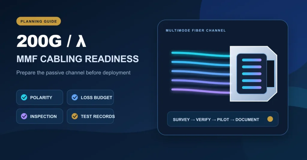
200 Gb/s per wavelength over multimode fiber is still an active standards-development topic, so cabling teams should prepare without treating a draft as a finished deployment specification. The practical work today is to inventory optical interfaces, document fiber paths, control connector polarity and cleanliness, and build measurable loss records. Those steps reduce migration risk while final reach, lane and test requirements remain tied to the approved standard and the selected equipment.
What the Current IEEE Work Means
The IEEE 802.3 Working Group lists P802.3ds as the project for 200 Gb/s per wavelength physical layers over multimode fiber. The official IEEE 802.3 ballot and review announcements show that the draft was in Task Force review during August 2026. That is a useful direction signal, but it is not permission to label an installed channel as compliant with a final standard that has not yet completed the process.
For planners, the distinction matters. A switch may advertise an aggregate rate such as 800G or 1.6T while using different lane counts, electrical interfaces, optical wavelengths or connector arrangements. A cabling decision must therefore begin with the exact host and optical specifications. The IEEE 802.3 project index should be checked for current project status, and procurement documents should identify any draft dependency explicitly.
Build a Readiness File Before Choosing Components
Record every active-equipment interface
Create an inventory with switch model, line-card port, supported module form factor, optical interface, target reach and required lane architecture. Include planned deployment dates and software or firmware dependencies. If the optic is not yet selected, mark the interface as undecided rather than filling the gap with an assumption.
This is especially important when comparing QSFP-DD and OSFP ecosystems. The cages, thermal envelopes and supported optical modules are not interchangeable simply because the front-panel speeds look similar. Our OSFP vs QSFP-DD compatibility checklist provides a separate host-side review.
Map the installed multimode fiber
Record fiber category, cable length, connector count, splice count, patching locations and any unknown sections. Existing OM3, OM4 or OM5 labels should be verified against installation records rather than inferred from jacket color alone. A short link can still fail if it contains excessive connections, contamination, poor terminations or undocumented routing.
Do not use a generic distance claim in place of the final equipment specification. Supported reach depends on the completed PHY definition and the actual optical module. The readiness file should leave the design target open until those two sources agree.
Control the Four Cabling Variables That Create Most Risk
| Variable | What to document now | Acceptance evidence |
|---|---|---|
| Polarity | End-to-end lane map, MPO method, key orientation and breakout sequence | Continuity and polarity result for every fiber position |
| Optical loss | Length, mated pairs, cassettes and splices in each path | Bidirectional loss result and reference method |
| End-face condition | Inspection and cleaning procedure for every connection | Pass image or inspection record before mating |
| Configuration control | Cable ID, port ID, drawing revision and change owner | As-built record linked to the test result |
Polarity and lane mapping
Higher lane rates do not eliminate the need for correct transmit-to-receive mapping. Define whether the channel uses duplex interfaces, native parallel optics or a breakout assembly. For MPO systems, specify Method A, B or C together with fiber count, pinned or unpinned gender and key orientation. See our MPO polarity deployment checklist for the procurement fields that should accompany a trunk or harness request.
Inspection and cleaning
Contamination can affect insertion loss and damage mated end faces. Inspect before connecting, clean when required and inspect again. Multi-fiber connectors deserve special care because one contaminated end face can disturb several lanes. The official Fluke Networks fiber polarity guidance is a useful reference for understanding duplex and array channel behavior; testing and cleaning procedures should also follow the equipment and test-instrument manufacturers.

A Practical Staged Migration Plan
- Survey: inventory ports, optics, trunks, patch panels and test history.
- Classify: separate verified reusable paths from unknown or damaged infrastructure.
- Model: build a channel diagram and provisional loss budget for each candidate link.
- Pilot: validate a small number of representative short, long and high-connection-count paths with the actual equipment.
- Accept: define pass/fail limits from the final standard and vendor documentation, then test consistently.
- Document: store results by cable and port ID, including test date, instrument and reference setup.
- Scale: release the wider rollout only after the pilot exposes no unresolved compatibility or workmanship issue.
A pilot should include the hardest realistic path, not only the cleanest laboratory link. Include the longest route, the highest connector count and a representative rack environment. If the design uses conversion modules or breakouts, test those exact components and document the lane mapping.
Questions to Put on an RFQ
- Which final or draft specification does the optical interface reference?
- What host platforms and firmware versions have been verified by the equipment vendor?
- What fiber category, connector type, polarity and maximum channel loss are required?
- Is the stated reach a channel limit or a simpler engineered link condition?
- Which inspection, continuity and optical-loss tests are required at handover?
- How will serial numbers, cable IDs and test files be matched?
These questions help prevent a cable purchase from being separated from the active-equipment design. DetwilerTech’s product center can be used to review available structured cabling categories, while final compatibility remains subject to the selected system specification.
Frequently Asked Questions
Is 200G per wavelength MMF already a final IEEE standard?
No. IEEE P802.3ds is standards work in progress as of the cited August 2026 review information. Check the official IEEE project status before placing compliance language in a specification or purchase order.
Will an existing OM4 link automatically support the new interface?
No. The jacket label alone does not confirm reach, loss, connector condition, polarity or equipment compatibility. Survey and test the complete channel against the final optic and host requirements.
Should cabling be replaced before the optics are selected?
Not automatically. First document the existing infrastructure and identify uncertain paths. Replacement or reuse should follow the final interface, reach and loss requirements plus pilot results.
Conclusion
Preparation for 200G per wavelength multimode fiber should focus on verified infrastructure, not speculative compliance claims. Build an accurate port and fiber inventory, control polarity and cleanliness, establish test records and validate representative links with the selected equipment. That work remains valuable even if the final standard or product roadmap changes.
Preparing a high-speed multimode fiber BOM or pilot? Send the host interface, optics plan, fiber category, route lengths, connector map and required test documentation through our Contact Us page. We can review assembly and documentation requirements without claiming active-system compatibility that has not been verified.
Author: DetwilerTech Technical Content Team. Standards status and equipment requirements can change; verify the latest official IEEE and vendor documents before deployment.

CUSTOMER DISCUSSION
Article Discussion
Read questions and experience from other customers, then add your own product or project feedback.
No published comments yet. Start the first useful discussion.
Sign in to comment
Registered customers use their account display name and can track moderation status from the account page.
Customer Login Create an Account