



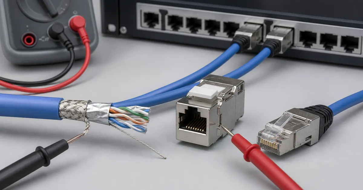
A shielded CAT6A component can look impressive on a product page: metal shell, foil, drain wire and a solid-looking rack panel. Yet shielding performance is not owned by any one part. It is created—or interrupted—at every interface.
The useful mental model is simple: shielding is a path, not a part. This guide helps buyers and installers review that path before approving cable, keystone jacks, modular plugs, patch cords and rack-side hardware.
Map the shield path before selecting products
Draw the channel from equipment to equipment and mark every transition. A typical path may include a shielded patch cord, patch panel or modular jack, horizontal cable, work-area jack and another patch cord. Each transition has a mechanical and electrical interface.
For every interface, ask:
- What surface carries shield contact?
- How is that contact maintained after termination and strain?
- Where is bonding or grounding intended to occur?
- Can installation practice accidentally isolate the shield?
Five continuity checkpoints
1. Cable construction and preparation
Record the overall shield format, pair shielding if present, drain wire, conductor construction, insulation diameter and cable outside diameter. Preparation length matters: removing too much shield can expose an unprotected section, while poor folding or contact can make the shield mechanically unstable.
Start with the actual shielded bulk cable construction, not the category label alone.
2. Jack or plug cable-entry geometry
The termination must accept the cable diameter, conductor layout and shield preparation without forcing sharp bends or loose clamping. A metal shell is useful only if it makes repeatable contact with the prepared shield and keeps that contact under normal cable movement.
Compare the cable-entry range and termination method across shielded keystone jacks and RJ45 modular plugs.
3. Strain relief and installation repeatability
Shield contact should not depend on one installer holding a foil fold in exactly the right place. Review the clamp, cable tie, boot or housing mechanism that maintains both shield contact and mechanical strain relief. The best sample is not the one perfect termination; it is a set of repeated terminations made with the intended tools and work instructions.
4. Rack-side bonding and equipment interface
A shielded jack installed in an isolated plastic carrier behaves differently from one designed into a bonded metal panel. Define the rack-side architecture, panel material, bonding hardware and equipment connection. Follow the project’s approved grounding and bonding design rather than inventing an extra path at installation time.
5. Patching and maintenance
The permanent link may be shielded while an unshielded patch cord is later installed during a move. Procurement lists, spares and labeling should make the required patching type obvious. Review the patch cord family as part of the same channel, not as a separate accessory.
| Interface | What to confirm | Common weak point |
|---|---|---|
| Cable to jack | Shield prep, diameter, clamp and strain relief | Foil contact changes between installers |
| Jack to panel | Metal contact or intended isolation | Shielded jack placed in an unplanned carrier |
| Panel to rack | Bonding hardware and project design | Paint, loose hardware or missing bond |
| Patch cord to port | Shielded plug and mating contact | Unshielded service replacement |
| Channel test | Exact sample topology and method | Component result treated as channel proof |
A practical sample-approval sequence
- Freeze the cable, jack/plug, panel and patch-cord combination.
- Document cable preparation and the intended termination tools.
- Build several samples, not only one showcase termination.
- Inspect shield contact, strain relief, bend radius and rack fit.
- Verify continuity using the project’s agreed method.
- Run the required link or channel test in the stated configuration.
- Keep an approved sample and work instruction for production reference.
How DetwilerTech supports interface review
Shield continuity crosses stamped metal parts, molded housings, cable-entry geometry and final assembly. DetwilerTech’s mold design, precision metal stamping, injection molding and assembly capabilities allow these interfaces to be reviewed together during an OEM project. Available inspection and network test equipment can support an agreed sample plan, but the buyer and supplier should define the exact configuration and acceptance criteria first.
Three conclusions a shielded sample cannot prove by itself
First, one carefully built sample does not prove that the installation process is repeatable. Ask multiple technicians or a production-style work sequence to terminate a small set. Second, continuity alone does not prove the required channel performance; the agreed cable, patching, connection count, length and test configuration still matter. Third, a component-level result does not automatically describe the building grounding system. Bonding and grounding belong to the approved project design and applicable installation practice.
Record each result with the exact sample configuration. Photographs of cable preparation, termination steps and rack contact points make later production and site troubleshooting much more useful than a pass/fail note without context.
Frequently asked questions
Does one shielded component make the whole channel shielded?
No. Shield continuity depends on compatible shielded cable, termination hardware, patching, rack-side bonding and installation. A single shielded component cannot repair a broken interface elsewhere.
Is a drain wire the same as the channel grounding path?
The drain wire can help maintain contact with a cable shield, but the complete path also includes the connector or jack shield, patch panel or equipment interface and the project grounding and bonding design.
What should be checked on a CAT6A shielded sample?
Check cable dimensions, shield preparation, strain relief, metal-to-metal contact, termination repeatability, rack fit, grounding method and the electrical test configuration required by the project.
Review the complete shield path before ordering
Compare DetwilerTech structured cabling components and send the planned cable, termination and rack configuration. We can identify interface questions and prepare a focused sample-review checklist.

CUSTOMER DISCUSSION
Article Discussion
Read questions and experience from other customers, then add your own product or project feedback.
No published comments yet. Start the first useful discussion.
Sign in to comment
Registered customers use their account display name and can track moderation status from the account page.
Customer Login Create an Account